
-
Home
-
Products
- Solution
- WHY JUNPU
- Services
- Resources
- News
- Contact Us

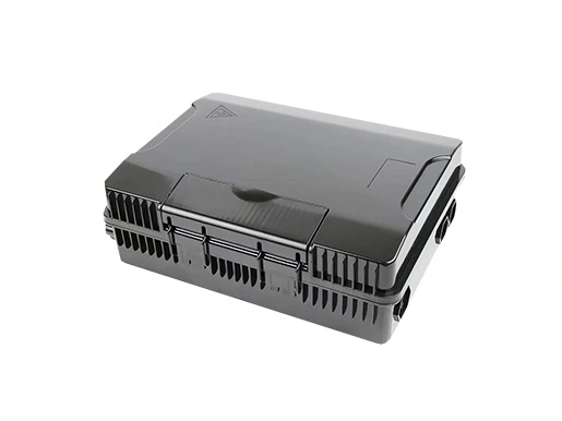
JUNPU 24 Core Terminal Box Fiber is in black color. The equipment is used as a termination point for the feeder cable to connect with drop cable in FTTx communication network system. The fiber splicing, splitting, distribution can be done in this box, and meanwhile it provides solid protection and management for the FTTx network building.
Total enclosed structure.
Material: PC+ABS,wet-proof、water-proof、dust-proof、anti-aging, protection level up to IP66.
Clamping for feeder cable and drop cable, fiber splicing, fixation, storage, distribution...etc all in one.
Cable, pigtails, and patch cords run through their own path without disturbing each other, cassette type SC adaptor installation, easy maintenance.
Distribution panel can be flipped up, feeder cable can be placed in a cup-joint way, easy for maintenance and installation.
Cabinet can be installed by the way of wall-mounted or poled-mounted, suitable for both indoor and outdoor uses.
Environmental requirement
Working temperature:-40℃~+85℃
Relative humidity:≤85%(+30℃)
Atmospheric pressure:70KPa~106Kpa
Main technical datasheet
Insertion loss:≤0.2dB
UPC return loss:≥50dB
APC return loss:≥60dB
Life of insertion and extraction:>1000 times
Thunder-proof technical datasheet
The grounding device is isolated with the cabinet, and isolation resistance is less than 2MΩ/500V(DC);
IR≥2MΩ/500V
The withstand voltage between the grounding device and cabinet is no less than 3000V(DC)/min, no puncture, no flashover; U≥3000V
Table 1 Model and configuration
Model | Description | Size(Pic 1) | Max Capacity | Installation Size(Pic 2) | Cable ways | ||
A*B*C(mm) | SC | LC | PLC | D*E (mm) | |||
JR-1001-F029 | Fiber Access Terminal | 340*250*110 | 24 | 48 | 1 x 1:16/ 3 x 1:8 | 145*120 | Cutted/uncut cable |
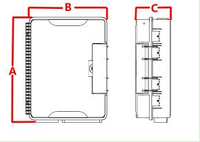
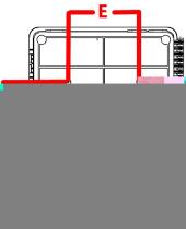
Pic 1 Box Size Pic 2 Box Size

1. Lid;2.Lock coat;3. Lock;4. Seal gasket;5. Splicing flap plate;6. Adaptor holder;7. Adaptor;8. Lid lock joint bracket;9. Lid lock clip;10. Base;11. Cable strengthens mound layer;12. Cable entrance;13. Lock panel;14. PLC mounting position
1. Wall-mounted installation
Drill 4 holes over the wall based on the size in Table 1, place the expansion bolt Φ7.5*40, place the box to match up the holes, and use the bolt to fasten.
2. Pole-mounted installation
Fix 1 set of the easy pole ring to the telecom pole.
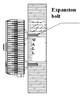
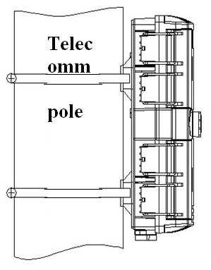
Pic 5 Wall mounted installation Pic 5 Pole ring installation
 Call us on:
  Email Us:
  Wanhua Science and Technology Park, No. 528, Shunfeng Road, Donghu Street, Linping District, Hangzhou City, Zhejiang Province